
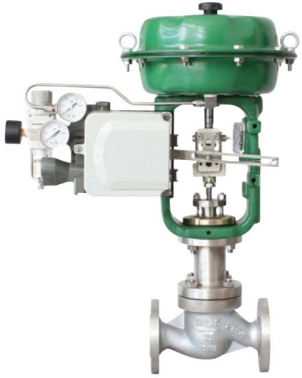
ZJHM Compact Pneumatic Diaphragm Sleeve Control Valve consists of a pneumatic multi-spring diaphragm actuator paired with a compact sleeve-type control valve. Its main features include:Balanced Trim Design – The balanced plug greatly reduces unbalanced forces, allowing for a higher permissible differential pressure and ensuring stable operation.Large Guiding Surface – The enlarged guiding area improves stability and reduces oscillation caused by vortex effects and impact forces.Low Noise Performance – Noise levels are approximately 10 dB lower than conventional single-seat or double-seat control valves.Simple Structure & Easy Maintenance – The design is straightforward, enabling convenient assembly, disassembly, and servicing.
European-style premium construction, precise control performance, excellent sealing, advanced design, and superior quality.
High-precision engineering, optimized structure, smooth flow, fast response, and a reliable alternative to imported products.
Low pressure loss, stable output force, high flow coefficient, and smooth, equal-section flow passage.
Wide control range, high flow-characteristic accuracy, top-guided structure, and easy handwheel operation.ange, high flow-characteristic accuracy, top-guided structure, and easy handwheel operation
| Technical Parameters and Performance - Valve Body | |
|---|---|
| Type | Straight-through cast ball valve |
| Nominal Diameter | 25, 32, 40, 50, 65, 80, 100, 125, 150, 200, 250, 300mm |
| Nominal Pressure | PN16, 40, 64bar |
| Flange Standard | JB/T79.1-94, 79.2-94, etc. |
| Material | Cast steel (ZG230-450), Stainless steel (ZG1Cr18Ni9Ti, ZG1Cr18Ni12Mo2Ti), etc. |
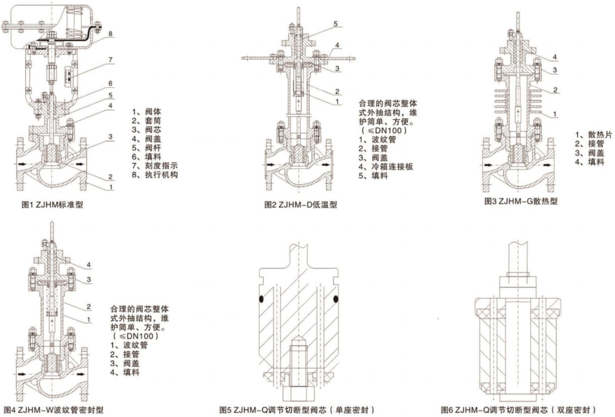
| Upper Bonnet | Standard type: -17~230℃Heat dissipation type: 230~450℃Low temperature type: -60~-196℃Bellows sealed type: -40~350℃ |
| Bonnet Type | Bolted type |
| Packing | V-type PTFE packing, Impregnated PTFE asbestos packing, Asbestos textile packing, Graphite packing |
| Structural Type | See Figures (1~4) for details |
| Technical Parameters and Performance - Inner Valve Components | |
|---|---|
| Valve Core Type | Pressure balanced valve core |
| Flow Characteristic | Equal percentage characteristic and linear characteristic |
| Material | Stainless steel (1Cr18Ni9Ti, 1Cr18Ni12Mo2Ti, 17-4PH, 9Cr18, 316L), Stainless steel surfacing Stellite alloy, Titanium and corrosion-resistant alloy, etc. |
| Technical Parameters and Performance - Actuator | |||||
|---|---|---|---|---|---|
| Type | ZHA/B multi-spring diaphragm actuator | ||||
| Model | ZHA/B-22 | ZHA/B-23 | ZHA/B-34 | ZHA/B-45 | ZHA/B-56 |
| Effective Area (cm²) | 350 | 350 | 560 | 900 | 1400 |
| Stroke (mm) | 10, 16 | 25 | 40 | 40, 60 | 100 |
| Spring Range (KPa) | 20~100 (Standard), 20-60, 60-100, 40-200, 80-240 | ||||
| Diaphragm Material | Nitrile rubber with nylon fabric, EPDM rubber with nylon fabric | ||||
| Supply Pressure | 140~400KPa | ||||
| Air Source Interface | RC1/4" | ||||
| Ambient Temperature | -30~70℃ | ||||
Valve action mode: Normally closed (B) - valve opens when air supply is lost (FO); Normally open (K) - valve closes when air supply is lost (FC)
Supplement: Positioner, air filter and pressure reducing device, hold-down valve, travel switch, valve position transmitter, handwheel mechanism, etc.
| Performance | ||||
|---|---|---|---|---|
| Item | Witdout Positioner | Witd Positioner | ||
| Basic Error % | ±5.0 | ±1.0 | ||
| Hysteresis % | ≤3.0 | ≤1.0 | ||
| Dead Band % | ≤3.0 | ≤0.4 | ||
| Start-End Point Deviation % | Start Point (Air Open) | ±2.5 | ±1.0 | |
| End Point (Air Open) | ±5.0 | ±1.0 | ||
| Start Point (Air Close) | ±5.0 | ±1.0 | ||
| End Point (Air Close) | ±2.5 | ±1.0 | ||
| Rated Stroke Deviation % | ≤2.5 | ≤2.5 | ||
| Leakage l/h | 0.01%×Valve Rated Capacity | 0.01%×Valve Rated Capacity | ||
| Adjustable Range R | 30:1 | 30:1 | ||
| Rated Flow Coefficient Kv, Rated Stroke, Matched Actuator Model | ||||||||||||
|---|---|---|---|---|---|---|---|---|---|---|---|---|
| Nominal Diameter DN (mm) | 25 | 32 | 40 | 50 | 65 | 80 | 100 | 125 | 150 | 200 | 250 | 300 |
| Valve Seat Diameter DN (mm) | 25 | 32 | 40 | 50 | 65 | 80 | 100 | 125 | 150 | 200 | 250 | 300 |
| Rated Flow Coefficient Kv - Linear | 11 | 17.6 | 27.5 | 44 | 69 | 110 | 176 | 275 | 440 | 690 | 1000 | 1600 |
| Rated Flow Coefficient Kv - Equal Percentage | 10 | 16 | 25 | 40 | 63 | 100 | 160 | 250 | 400 | 630 | 900 | 1440 |
| Rated Stroke L (mm) | 16 | 25 | 40 | 60 | 100 | |||||||
| Matched Actuator Model | ZHA/B-22 | ZHA/B-23 | ZHA/B-34 | ZHA/B-45 | ZHA/B-56 | |||||||
| Allowable pressure difference | ||||||||||||||
|---|---|---|---|---|---|---|---|---|---|---|---|---|---|---|
| Nominal Diameter DN (mm) | 25 | 32 | 40 | 50 | 65 | 80 | 100 | 125 | 150 | 200 | 250 | 300 | ||
| Valve Seat Diameter DN (mm) | 25 | 32 | 40 | 50 | 65 | 80 | 100 | 125 | 150 | 200 | 250 | 300 | ||
| Actuator | ZHA/B-22 | ZHA/B-23 | ZHA/B-34 | ZHA/B-45 | ZHA/-56 | |||||||||
| Action Mode | Air Source Pressure (Kpa) | Spring Range (Kpa) | Allowable Pressure Difference △(bar) | |||||||||||
| Air Close | 140 | 20~100 | 30 | 22.5 | 22.5 | 19.5 | 23.6 | 20.4 | 16.7 | 14.1 | 14.1 | 14.1 | 6.5 | 5.5 |
| 250 | 20~100 | 64 | 64 | 64 | 64 | 64 | 64 | 64 | 64 | 64 | 64 | 15.5 | 14 | |
| 400 | 40~200 | 64 | 6.4 | 64 | 64 | 64 | 64 | 64 | 64 | 64 | 64 | 40.8 | 40.8 | |
| Air Open | 140 | 20~100 | 15 | 11.3 | 11.3 | 9.8 | 11.8 | 10.2 | 8.4 | 7.1 | 7.1 | 5.7 | 6.5 | 5.5 |
| 250 | 40~200 | 45 | 33.8 | 33.8 | 29.3 | 35.4 | 30.6 | 25.1 | 21.2 | 21.2 | 17.1 | 18 | 15.5 | |
| 400 | 80~240 | 64 | 64 | 64 | 64 | 64 | 64 | 58.5 | 49.4 | 49.4 | 40 | 40.8 | 36.5 | |
Note: For the bellows-sealed regulating valve, the maximum allowable pressure difference is 10 bar. If the value in the table is less than 10 bar, it remains unchanged; if it is greater than 10 bar, it is taken as 10 bar.
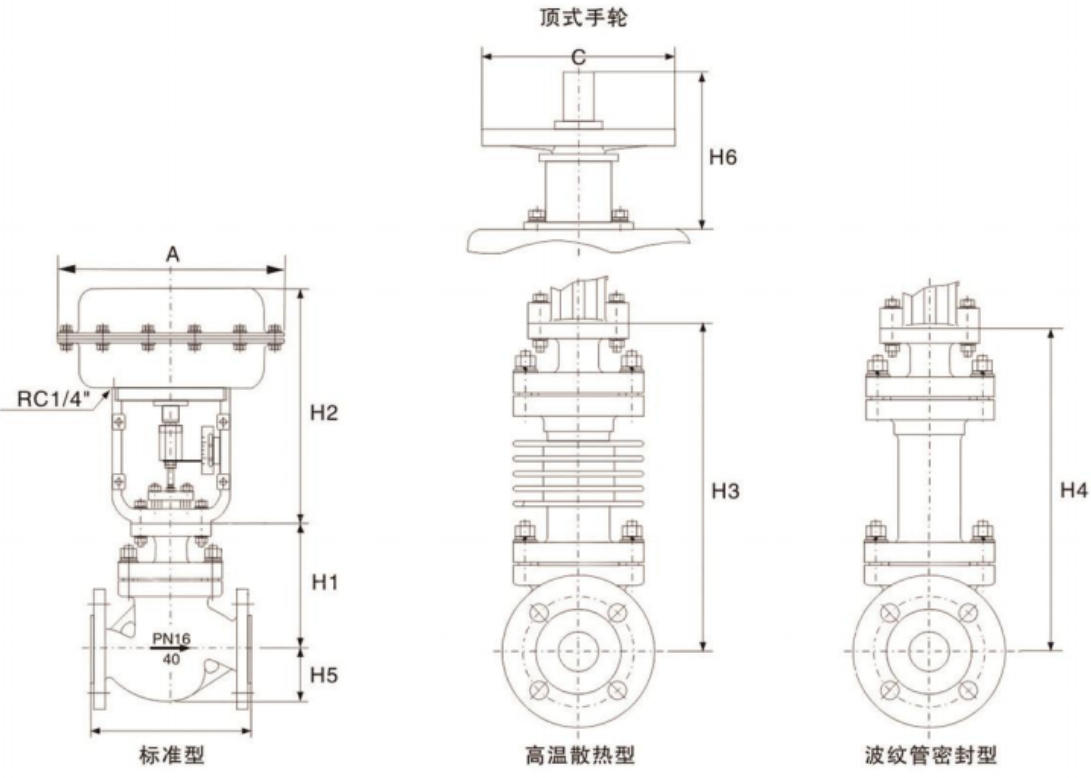
| Outline Dimensions and Weight(mm) | ||||||||||||
|---|---|---|---|---|---|---|---|---|---|---|---|---|
| Nominal Diameter | 25 | 32 | 40 | 50 | 65 | 80 | 100 | 125 | 150 | 200 | 250 | 300 |
| L - PN16/40 | 184 | 220 | 222 | 254 | 276 | 298 | 352 | 410 | 451 | 600 | 730 | 850 |
| L - PN64 | 210 | 251 | 251 | 286 | 311 | 337 | 394 | 457 | 508 | 650 | 775 | 900 |
| A | 285 | 285 | 285 | 285 | 360 | 360 | 360 | 470 | 470 | 470 | 580 | 580 |
| H1 - PN16/40 | 128 | 152 | 152 | 160 | 205 | 205 | 208 | 273 | 330 | 364 | ||
| H1 - PN64 | 140 | 160 | 160 | 180 | 210 | 210 | 220 | 290 | 340 | 370 | ||
| H2 | 298 | 298 | 298 | 298 | 380 | 380 | 380 | 510 | 510 | 510 | ||
| H3 - PN16/40 | 208 | 224 | 228 | 228 | 334 | 334 | 342 | 408 | 453 | 482 | ||
| H3 - PN64 | 220 | 240 | 240 | 240 | 350 | 350 | 360 | 420 | 470 | 500 | ||
| H4 | 338 | 402 | 402 | 405 | 627 | 628 | 635 | 698 | 702 | 728 | ||
| H5 - PN16/40 | 58 | 68 | 73 | 80 | 90 | 98 | 108 | 123 | 140 | 168 | ||
| H5 - PN64 | 68 | 75 | 83 | 88 | 100 | 105 | 125 | 148 | 170 | 203 | ||
| C | 220 | 220 | 220 | 220 | 270 | 270 | 270 | 320 | 320 | 320 | ||
| H6 | 180 | 180 | 180 | 180 | 236 | 236 | 236 | 310 | 310 | 310 | ||
| Weight (kg) - PN16/40 | 22 | 24 | 32 | 38 | 62 | 67 | 83 | 132 | 160 | 245 | ||
| Weight (kg) - PN64 | 25 | 30 | 42 | 52 | 78 | 82 | 102 | 170 | 190 | 285 |
Note:
1. The weights shown in the table are for the standard type without accessories. Side-mounted handwheels can also be installed.
2. The flange and the flange end face distance can be manufactured according to the user's specified standards, such as: ANSI JIS, DIN standards.
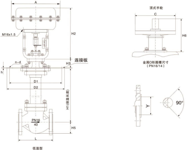
| Dimensions and weight(mm) | ||||||||||||
|---|---|---|---|---|---|---|---|---|---|---|---|---|
| Nominal Diameter | 25 | 32 | 40 | 50 | 65 | 80 | 100 | 125 | 150 | 200 | 250 | 300 |
| L - PN16/40 | 184 | 220 | 222 | 254 | 276 | 298 | 352 | 410 | 451 | 600 | 730 | 850 |
| L - PN64/100 | 210 | 251 | 251 | 286 | 311 | 337 | 394 | 457 | 508 | 650 | 775 | 900 |
| A | 285 | 285 | 285 | 285 | 360 | 360 | 360 | 470 | 470 | 470 | ||
| H1 | 700 | 700 | 700 | 700 | 700 | 700 | 700 | 700 | 700 | 700 | ||
| H2 | 298 | 298 | 298 | 298 | 380 | 380 | 380 | 510 | 510 | 510 | ||
| H3 | 88 | 88 | 88 | 88 | 94 | 94 | 940 | 110 | 110 | 110 | ||
| H5 - PN16/40 | 58 | 68 | 73 | 80 | 90 | 98 | 108 | 123 | 140 | 168 | ||
| H5 - PN64/100 | 68 | 75 | 83 | 88 | 100 | 105 | 125 | 148 | 170 | 203 | ||
| D1 - PN16/40 | 230 | 250 | 270 | 305 | 342 | 375 | 430 | 490 | 556 | 665 | ||
| D1 - PN64/100 | 270 | 305 | 342 | 375 | 430 | 490 | 556 | 665 | 665 | 765 | ||
| D2 - PN16/40 | 310 | 335 | 355 | 390 | 430 | 465 | 520 | 585 | 660 | 770 | ||
| D2 - PN64/100 | 355 | 390 | 430 | 465 | 520 | 585 | 600 | 770 | 770 | 890 | ||
| h | 15 | 15 | 15 | 15 | 18 | 18 | 18 | 20 | 20 | 20 | ||
| n-d - PN16/40 | 8-12 | 8-12 | 8-14 | 8-14 | 10-14 | 10-14 | 12-16 | 14-16 | 16-16 | 18-16 | ||
| n-d - PN64/100 | 8-14 | 8-14 | 10-14 | 10-14 | 12-16 | 14-16 | 16-16 | 18-16 | 18-16 | 18-16 | ||
| Y | 45 | 60 | 65 | 75 | 90 | 104 | 135 | 165 | 195 | 245 | ||
| C | 220 | 220 | 220 | 220 | 265 | 265 | 265 | 315 | 315 | 315 | ||
| H6 | 180 | 180 | 180 | 180 | 240 | 240 | 240 | 304 | 304 | 304 | ||
| Weight (kg) | 48 | 52 | 60 | 68 | 90 | 105 | 143 | 210 | 282 | 315 | ||
Note:
1. The insulation length is taken as 700mm for example. The weight in the table is the PN16 data. Side-mounted handwheels can also be installed.
2. The valve flange and the flange end face distance can be manufactured according to the user's specified standards, such as ANSI, JIS, and DIN standards.