
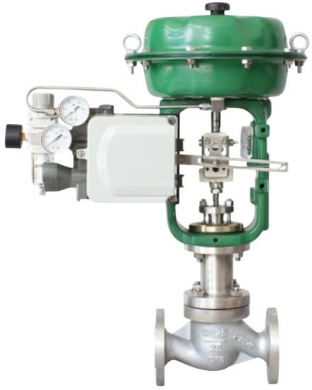
The ZJHP compact pneumatic diaphragm single-seat control valve consists of a single-seat valve body and a pneumatic actuator. The compact single-seat design features a tight structure, light weight, sensitive operation, streamlined S-shaped flow channel, low pressure drop, large flow capacity, accurate flow characteristics, and convenient assembly and disassembly.The cage-type quick-removal design solves the problems of traditional threaded-in valve seats, such as difficult on-site maintenance and high servicing costs.It is suitable for applications requiring strict leakage control, low differential pressure across the valve, and media with certain viscosity or small amounts of fibrous content.
European-style precision construction, accurate control, excellent sealing performance, advanced design, and superior quality
Exceptional craftsmanship, optimized structure, smooth flow, fast response, and a reliable alternative to imported products
Low pressure loss, stable output force, high flow coefficient, smooth flow channels with equal cross-sections, wide control range, high flow-characteristic accuracy, top-guided structure, and easy handwheel operation
| Technical Parameters and Performance - Valve Body | |
|---|---|
| Type | Straight-through single-seat cast ball valve |
| Nominal Diameter | 15, 20, 25, 32, 40, 50, 65, 80, 100, 125, 150, 200mm |
| Nominal Pressure | PN16, 40, 64bar |
| Flange Standard | JB/T79.1-94, 79.2-94, etc. |
| Material | Cast steel (ZG230-450), Stainless steel (ZG1Cr18Ni9Ti, ZG1Cr18Ni12Mo2Ti), etc. |
| Upper Bonnet | Standard type: -17~230℃Heat dissipation type: 230~450℃Low temperature type: -60~-196℃Bellows sealed type: -40~350℃ |
| Bonnet Type | Bolted type |
| Packing | V-type PTFE packing, Impregnated PTFE asbestos packing, Asbestos textile packing, Graphite packing |
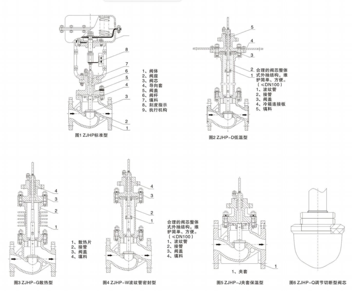
| Structural Type | (See Figure 1~Figure 5 for details) |
| Technical Parameters and Performance - Inner Valve Components | |
|---|---|
| Valve Core Type | Single-seat plunger type valve core |
| Flow Characteristic | Equal percentage characteristic and linear characteristic |
| Material | Stainless steel (1Cr18Ni9Ti, 1Cr18Ni12Mo2Ti, 17-4PH, 9Cr18, 316L), Stainless steel surfacing Stellite alloy, Titanium and corrosion-resistant alloy, etc. |
| Technical Parameters and Performance - Actuator | |
|---|---|
| Type | ZHA/B multi-spring diaphragm actuator |
| Model | ZHA/B-22ZHA/B-23ZHA/B-34ZHA/B-45ZHA/B-56 |
| Effective Area (cm²) | 3503505609001400 |
| Stroke (mm) | 10, 16254040, 60100 |
| Spring Range (KPa) | 20~100 (Standard), 20-60, 60-100, 40-200, 80-240 |
| Diaphragm Material | Nitrile rubber with nylon fabric, EPDM rubber with nylon fabric |
| Supply Pressure | 140~400KPa |
| Air Source Interface | RC1/4" |
| Ambient Temperature | -30~70℃ |
| Performance | |||||
|---|---|---|---|---|---|
| Item | Without Positioner | With Positioner | |||
| Basic Error % | ±5.0 | ±1.0 | |||
| Hysteresis % | ≤3.0 | ≤1.0 | |||
| Dead Band % | ≤3.0 | ≤0.4 | |||
| Start-End Point Deviation % | Flow Open | Start Point | ±2.5 | ±1.0 | |
| End Point | ±5.0 | ±1.0 | |||
| Flow Close | Start Point | ±5.0 | ±1.0 | ||
| End Point | ±2.5 | ±1.0 | |||
| Rated Stroke Deviation % | ≤2.5 | ||||
| Leakage l/h | 0.01%×Valve Rated Capacity | ||||
| Adjustable Range R | 30:1 | ||||
| Rated Flow Coefficient Kv, Rated Stroke, Matched Actuator Model | ||||||||||||||
|---|---|---|---|---|---|---|---|---|---|---|---|---|---|---|
| Nominal Diameter DN (mm) | 15/20 | 25 | 32 | 40 | 50 | 65 | 80 | 100 | 125 | 150 | 200 | |||
| Valve Seat Diameter DN (mm) | 10 | 12 | 15 | 20 | 25 | 32 | 40 | 50 | 65 | 80 | 100 | 125 | 150 | 200 |
| Rated Flow Coefficient Kv - Linear | 1.8 | 2.8 | 4.4 | 6.9 | 11 | 17.6 | 27.5 | 44 | 69 | 110 | 176 | 275 | 440 | 690 |
| Rated Flow Coefficient Kv - Equal Percentage | 1.6 | 2.5 | 4.0 | 6.3 | 10 | 16 | 25 | 40 | 63 | 100 | 160 | 250 | 400 | 630 |
| Rated Stroke L (mm) | 10 | 16 | 25 | 40 | 60 | |||||||||
| Matched Actuator Model | ZHA/B-22 | ZHA/B-23 | ZHA/B-34 | ZHA/B-45 | ||||||||||
| Allowable Pressure Difference | ||||||||||||||||
|---|---|---|---|---|---|---|---|---|---|---|---|---|---|---|---|---|
| Nominal Diameter DN (mm) | 15/20 | 25 | 32 | 40 | 50 | 65 | 80 | 100 | 125 | 150 | 200 | |||||
| Seat Diameter DN (mm) | 10 | 12 | 15 | 20 | 25 | 32 | 40 | 50 | 65 | 80 | 100 | 125 | 150 | 200 | ||
| Actuator | ZHA/B-22 | ZHA/B-23 | ZHA/B-34 | ZHA(B)-45 | ||||||||||||
| Action Mode | Air Supply Pressure (Kpa) | Spring Range (Kpa) | Allowable Pressure Difference Δ(bar) | |||||||||||||
| Air-to-Close | 140 | 20~100 | 64 | 61.9 | 39.6 | 22.3 | 21.4 | 8.7 | 5.6 | 3.5 | 3.4 | 2.2 | 1.4 | 1.5 | 1 | 0.6 |
| 250 | 20~100 | 64 | 64 | 64 | 64 | 64 | 56.8 | 36.4 | 23 | 22.1 | 14.3 | 9.1 | 9.5 | 6.6 | 3.7 | |
| 400 | 40~200 | 64 | 64 | 64 | 64 | 64 | 64 | 50.4 | 31.8 | 30.6 | 19.8 | 2.6 | 13.2 | 9.2 | 5.2 | |
| Air-to-Open | 140 | 20~100 | 44.6 | 30.9 | 19.8 | 11.6 | 7 | 4.4 | 2.8 | 1.8 | 11.7 | 1.1 | 0.7 | 0.7 | 0.5 | 0.3 |
| 250 | 40~200 | 64 | 64 | 59.4 | 33.4 | 21.4 | 13.1 | 8.4 | 5.3 | 5.1 | 3.3 | 2.1 | 2.2 | 1.5 | 0.9 | |
| 400 | 80~240 | 64 | 64 | 64 | 64 | 49.9 | 30.5 | 19.5 | 12.5 | 11.8 | 7.8 | 5 | 5.1 | 3.6 | 2.1 | |
Note:For bellows-sealed control valves, the maximum allowable pressure difference is 10 bar. If the value in the table is less than 10 bar, it remains unchanged; if it is greater than 10 bar, it is taken as 10 bar.
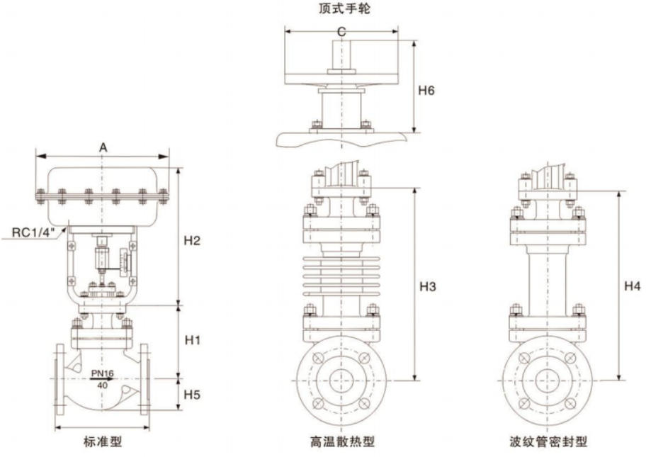
| Outline Dimensions and Weight(mm) | |||||||||||
|---|---|---|---|---|---|---|---|---|---|---|---|
| Nominal Diameter | 15/20 | 25 | 32 | 40 | 50 | 65 | 80 | 100 | 125 | 150 | 200 |
| L - PN16/40 | 181 | 184 | 220 | 222 | 254 | 276 | 298 | 352 | 410 | 451 | 600 |
| L - PN64 | 206 | 210 | 251 | 251 | 286 | 311 | 337 | 394 | 457 | 508 | 650 |
| A | 285 | 285 | 285 | 285 | 285 | 360 | 360 | 360 | 470 | 470 | 470 |
| H1 - PN16/40 | 128 | 128 | 152 | 152 | 160 | 205 | 205 | 208 | 273 | 330 | 364 |
| H1 - PN64 | 140 | 140 | 160 | 160 | 180 | 210 | 210 | 220 | 290 | 340 | 370 |
| H2 | 298 | 298 | 298 | 298 | 298 | 380 | 380 | 380 | 510 | 510 | 510 |
| H3 - PN16/40 | 208 | 208 | 224 | 228 | 228 | 334 | 334 | 342 | 408 | 453 | 482 |
| H3 - PN64 | 220 | 220 | 240 | 240 | 240 | 350 | 350 | 360 | 420 | 470 | 500 |
| H4 | 238 | 338 | 402 | 402 | 405 | 627 | 628 | 635 | 698 | 702 | 728 |
| H5 - PN16/40 | 53 | 58 | 68 | 73 | 80 | 90 | 98 | 108 | 123 | 140 | 168 |
| H5 - PN64 | 63 | 68 | 75 | 83 | 88 | 100 | 105 | 125 | 148 | 170 | 203 |
| C | 220 | 220 | 220 | 220 | 220 | 270 | 270 | 270 | 320 | 320 | 320 |
| H6 | 180 | 180 | 180 | 180 | 180 | 236 | 236 | 236 | 310 | 310 | 310 |
| Weight (kg) - PN16/40 | 21 | 22 | 24 | 32 | 38 | 62 | 67 | 83 | 132 | 160 | 245 |
| Weight (kg) - PN64 | 24 | 25 | 30 | 42 | 52 | 78 | 82 | 102 | 170 | 190 | 285 |
Note
1. The weight in the table is standard data without accessories. Side-mounted handwheels can also be installed.
2. Valve flanges and flange end face distances can be manufactured according to user-specified standards, such as ANSI, JIS, DIN standards.
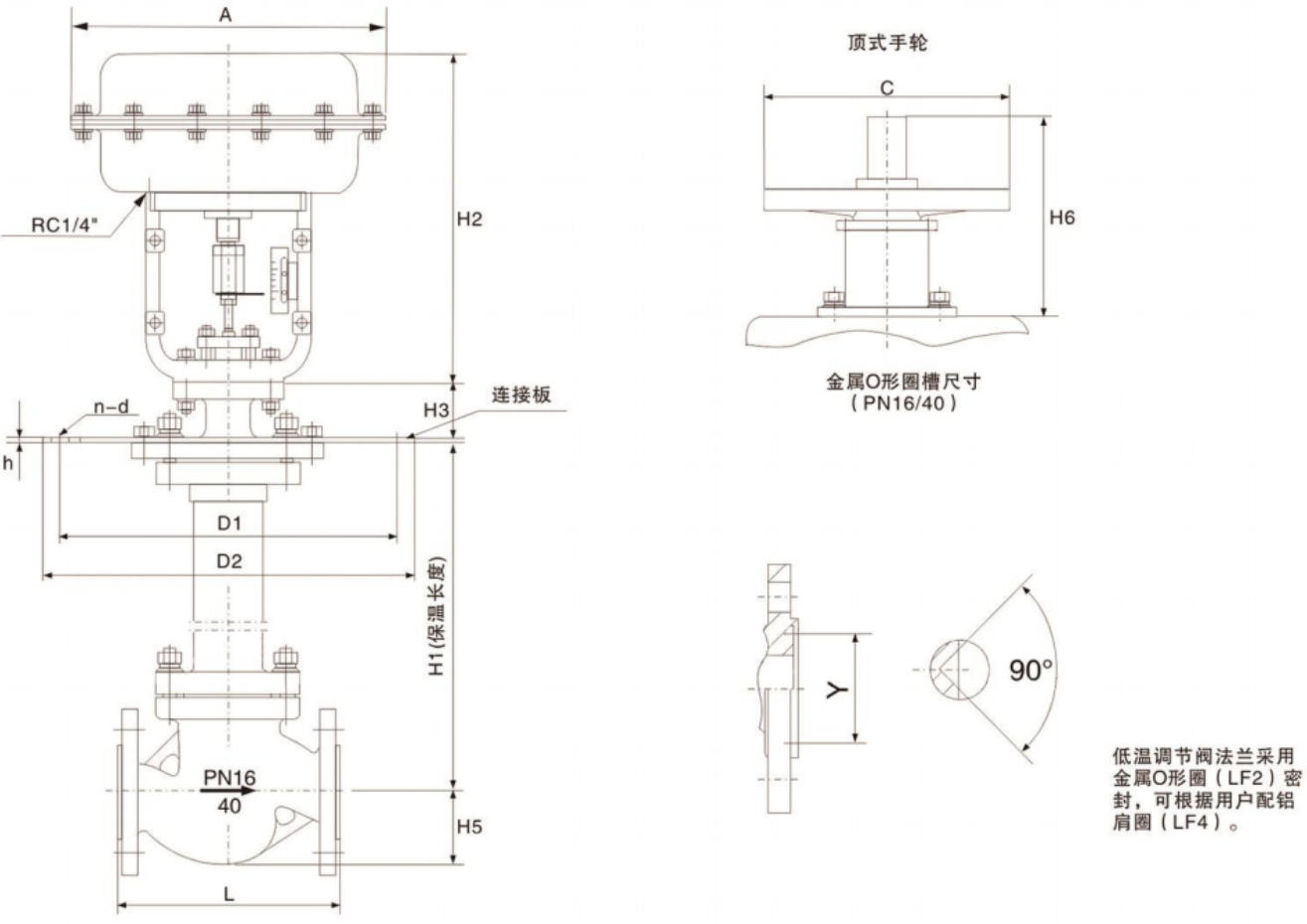
| Outline Dimensions and Weight(mm) | |||||||||||
|---|---|---|---|---|---|---|---|---|---|---|---|
| Nominal Diameter | 15/20 | 25 | 32 | 40 | 50 | 65 | 80 | 100 | 125 | 150 | 200 |
| L - PN16/40 | 181 | 184 | 220 | 222 | 254 | 276 | 298 | 352 | 410 | 451 | 600 |
| L - PN64 | 206 | 210 | 251 | 251 | 286 | 311 | 337 | 394 | 457 | 508 | 650 |
| A | 285 | 285 | 285 | 285 | 285 | 360 | 360 | 360 | 470 | 470 | 470 |
| H1 | 700 | 700 | 700 | 700 | 700 | 700 | 700 | 700 | 700 | 700 | 700 |
| H2 | 298 | 298 | 298 | 298 | 298 | 380 | 380 | 380 | 510 | 510 | 510 |
| H3 | 88 | 88 | 88 | 88 | 88 | 94 | 94 | 94 | 110 | 110 | 110 |
| H5 - PN16/40 | 53 | 58 | 68 | 73 | 80 | 90 | 98 | 108 | 123 | 140 | 168 |
| H5 - PN64 | 63 | 68 | 75 | 83 | 88 | 100 | 105 | 125 | 148 | 170 | 203 |
| D1 - PN16/40 | 230 | 230 | 250 | 270 | 305 | 342 | 375 | 430 | 490 | 556 | 665 |
| D1 - PN64 | 270 | 270 | 305 | 342 | 375 | 430 | 490 | 556 | 665 | 665 | 765 |
| D2 - PN16/40 | 310 | 310 | 335 | 355 | 390 | 430 | 465 | 520 | 585 | 660 | 770 |
| D2 - PN64 | 355 | 355 | 390 | 430 | 465 | 520 | 585 | 600 | 770 | 770 | 890 |
| h | 15 | 15 | 15 | 15 | 15 | 18 | 18 | 18 | 20 | 20 | 20 |
| n-d - PN16/40 | 8-12 | 8-12 | 8-12 | 8-14 | 8-14 | 10-14 | 10-14 | 12-16 | 14-16 | 16-16 | 18-16 |
| n-d - PN64 | 8-14 | 8-14 | 8-14 | 10-14 | 10-14 | 12-16 | 14-16 | 16-16 | 18-16 | 18-16 | 18-16 |
| Y | 45 | 45 | 60 | 65 | 75 | 90 | 104 | 135 | 165 | 195 | 245 |
| C | 220 | 220 | 220 | 220 | 220 | 270 | 270 | 270 | 320 | 230 | 320 |
| H6 | 180 | 180 | 180 | 180 | 180 | 236 | 236 | 236 | 310 | 310 | 310 |
| Weight (kg) | 40 | 48 | 52 | 60 | 68 | 90 | 105 | 143 | 210 | 282 | 315 |
Note:
1. The insulation length is taken as 700mm. The weight in the table represents the PN16 data. Side-mounted handwheels can also be installed.
2. The valve flange and the distance from the flange end face can be manufactured according to the user's specified standards, such as ANSI, JIS, and DIN standards.
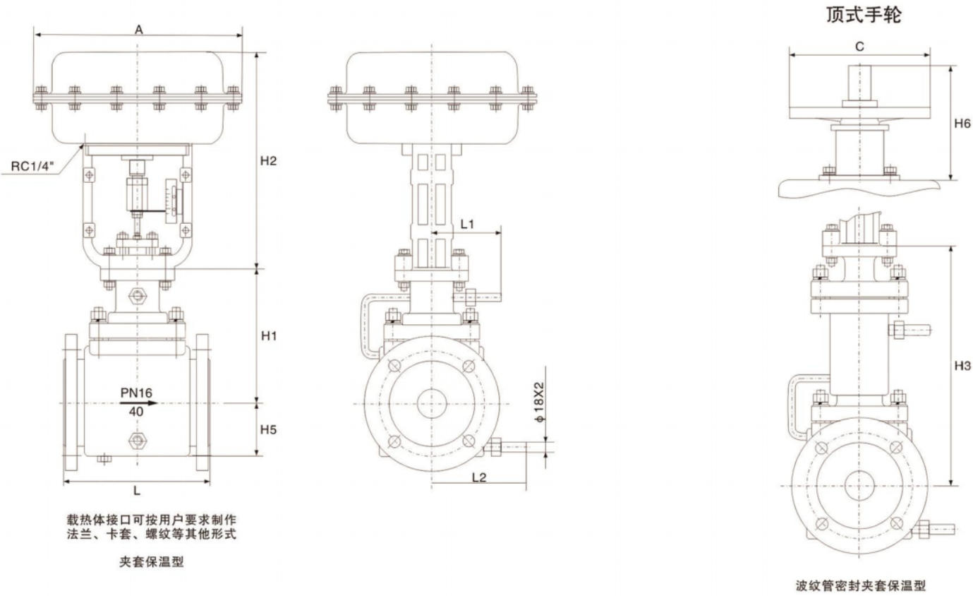
| Outline Dimensions and Weight(mm) | |||||||||||
|---|---|---|---|---|---|---|---|---|---|---|---|
| Nominal Diameter | 15/20 | 25 | 32 | 40 | 50 | 65 | 80 | 100 | 125 | 150 | 200 |
| L | 181 | 184 | 220 | 222 | 254 | 276 | 298 | 352 | 410 | 451 | 600 |
| A | 285 | 285 | 285 | 285 | 285 | 360 | 360 | 360 | 470 | 470 | 470 |
| H1 | 152 | 152 | 177 | 177 | 183 | 221 | 221 | 230 | 315 | 355 | 385 |
| H2 | 298 | 298 | 298 | 298 | 298 | 380 | 380 | 380 | 510 | 510 | 510 |
| H3 | 220 | 220 | 240 | 240 | 240 | 350 | 350 | 360 | 420 | 470 | 500 |
| H5 | 75 | 81 | 89 | 95 | 109 | 121 | 133 | 146 | 160 | 180 | 210 |
| L1 | 101 | 101 | 108 | 108 | 108 | 123 | 123 | 123 | 140 | 140 | 140 |
| L2 | 126 | 126 | 126 | 130 | 141 | 156 | 170 | 180 | 200 | 220 | 265 |
| C | 220 | 220 | 220 | 220 | 220 | 270 | 270 | 270 | 320 | 320 | 320 |
| H6 | 180 | 180 | 180 | 180 | 180 | 236 | 236 | 236 | 310 | 310 | 310 |
| Flange Specification DN | 40 | 40 | 50 | 65 | 80 | 100 | 125 | 150 | 200 | 250 | 300 |
| Weight (kg) | 26 | 27 | 35 | 44 | 56 | 84 | 88 | 109 | 185 | 202 | 305 |
Note:
1. The weights shown in the table are for PN16 data. Side-mounted handwheels can also be installed.
2. The flange and the flange end face distance can be manufactured according to the user's specified standards, such as ANSI, JIS, or DIN standards.