
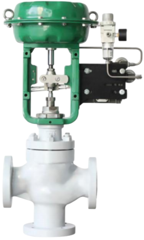
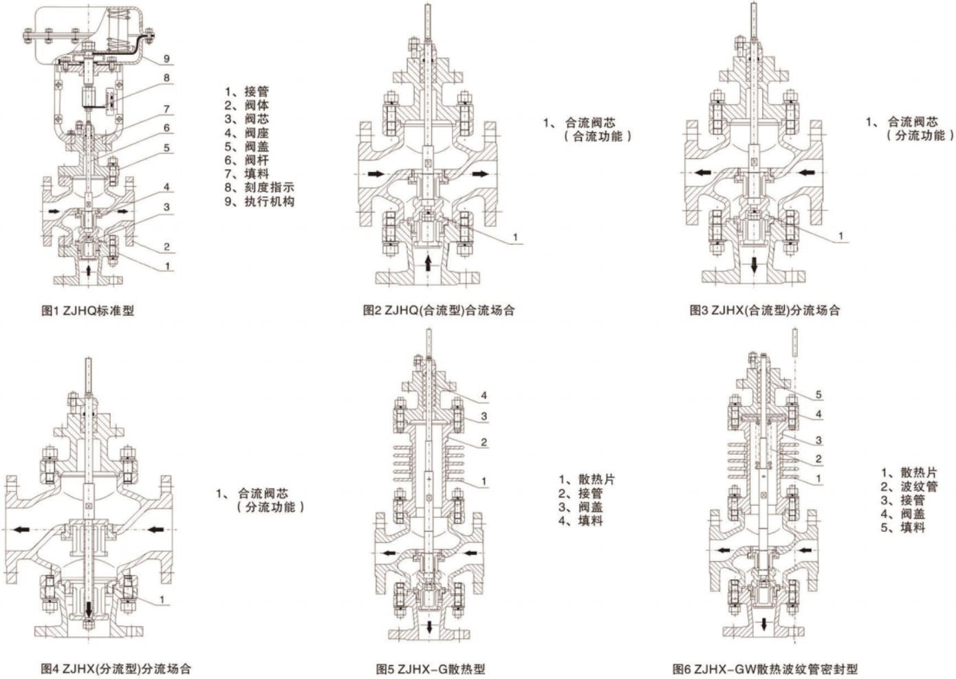
The ZJHO Pneumatic Three-Way Converging Control Valve and the ZJHX Pneumatic Three-Way Diverting Control Valve are composed of a pneumatic multi-spring diaphragm actuator paired with a three-way control valve body.The new ZHA/B multi-spring actuator replaces the older ZMA/B actuator series, offering advantages such as reduced height, lighter weight, and easier installation and maintenance.The three-way valve plug adopts a cylindrical thin-wall window structure with side-guided trim, providing excellent stability and flow characteristics. These valves are commonly used for proportional control or bypass regulation, and are particularly suitable for fluid temperature control systems in petrochemical heat exchangers.A single three-way valve can replace two single-seat or double-seat control valves, significantly reducing space requirements and saving on installation piping and overall cost.
European-style refined construction, precise control, excellent sealing performance, advanced design, and superior quality.
High-precision engineering, optimized structural design, smooth flow, fast response, and a reliable alternative to imported products.
Low pressure loss, stable output force, high flow coefficient, and a smooth, equal-section flow passage.
Wide control range, high flow-characteristic accuracy, top-guided structure, and easy handwheel operation.
| Technical Parameters and Performance - Valve Body | |
|---|---|
| Type | Straight-through cast globe valve |
| Nominal Diameter | Converging valve: 25~300; Diverging valve: 80~300 |
| Nominal Pressure | PN16, 40, 64bar |
| Flange Standard | JB/T79.1-94, 79.2-94, etc. |
| Material | Cast steel (ZG230-450), stainless steel (ZG1Cr18Ni9Ti, ZG1Cr18Ni12Mo2Ti), etc. |
| Upper Bonnet | Standard type: -17~230℃; Heat dissipation type: 230~450℃; Bellows sealed type: -40~350℃ |
| Bonnet Type | Bolted type |
| Packing | V-type PTFE packing, impregnated PTFE asbestos packing, graphite packing |
| Structural Type | (See Figures 1~6 for details) |
| Technical Parameters and Performance - Inner Valve Components | |
|---|---|
| Valve Core Type | Thin-walled cylindrical valve core |
| Flow Characteristic | Equal percentage characteristic and linear characteristic |
| Material | Stainless steel (1Cr18Ni9Ti, 1Cr18Ni12Mo2Ti, 17-4PH, 9Cr18, 316L), stainless steel surfacing Stellite alloy, titanium and corrosion-resistant alloy, etc. |
| Technical Parameters and Performance - Actuator | |||||
|---|---|---|---|---|---|
| Type | ZHA/B Multi-spring Diaphragm Actuator | ||||
| Model | ZHA/B-22 | ZHA/B-23 | ZHA/B-34 | ZHA/B-45 | ZHA/B-56 |
| Effective Area (cm²) | 350 | 350 | 560 | 900 | 1400 |
| Stroke (mm) | 10, 16 | 25 | 40 | 40, 60 | 100 |
| Spring Range (KPa) | 20~100 (Standard), 20-60, 60-100, 40-200, 80-240 | ||||
| Diaphragm Material | Nitrile rubber with nylon fabric, EPDM rubber with nylon fabric | ||||
| Supply Pressure | 140~400KPa | ||||
| Air Source Interface | RC1/4" | ||||
| Ambient Temperature | -30~70℃ | ||||
Valve operating mode:
Normally closed (B) - valve opens when air supply is lost (FO); Normally open (K) - valve closes when air supply is lost (FC).
Accessories: Positioner, air filter and pressure reducing device, hold-down valve, travel switch, valve position transmitter, handwheel mechanism, etc.
| Performance | Item | Without Positioner | With Positioner |
| Basic Error % | ±6.0 | ±1.5 | |
| Hysteresis % | ≤5.0 | ≤1.5 | |
| Dead Band % | ≤4.0 | ≤0.6 | |
| Start Point (Air Open) | ±2.5 | ±1.5 | |
| Start-End Point Deviation % | End Point (Air Open) | ±6.0 | ±1.5 |
| Start Point (Air Close) | ±6.0 | ±1.5 | |
| End Point (Air Close) | ±2.5 | ±1.5 | |
| Rated Stroke Deviation % | ≤2.5 | ≤2.5 | |
| Leakage (l/h) | 0.1%×Valve Rated Capacity | 0.1%×Valve Rated Capacity | |
| Adjustable Range R | 30:1 | 30:1 |
| Performance | |||
|---|---|---|---|
| Item | Without Positioner | With Positioner | |
| Basic Error % | ±6.0 | ±1.5 | |
| Hysteresis % | ≤5.0 | ≤1.5 | |
| Dead Band % | ≤4.0 | ≤0.6 | |
| Start-End Point Deviation % | Start Point (Air Open) | ±2.5 | ±1.5 |
| End Point (Air Open) | ±6.0 | ±1.5 | |
| Start Point (Air Close) | ±6.0 | ±1.5 | |
| End Point (Air Close) | ±2.5 | ±1.5 | |
| Rated Stroke Deviation % | ≤2.5 | ≤2.5 | |
| Leakage (l/h) | 0.1%×Valve Rated Capacity | ||
| Adjustable Range R | 30:1 | ||
| Rated Flow Coefficient Kv, Rated Stroke, Matched Actuator Model, Allowable Pressure Difference | ||||||||||||
|---|---|---|---|---|---|---|---|---|---|---|---|---|
| Nominal Diameter DN (mm) | 25 | 32 | 40 | 50 | 65 | 80 | 100 | 125 | 150 | 200 | 250 | 300 |
| Rated Flow Coefficient Kv - Converging Valve | 8.5 | 13 | 21 | 34 | 53 | 85 | 135 | 210 | 340 | 535 | 800 | 1360 |
| Rated Flow Coefficient Kv - Diverging Valve | - | - | - | - | - | 85 | 135 | 210 | 340 | 535 | 800 | 1360 |
| Rated Stroke L (mm) | 16 | 25 | 40 | 60 | 100 | |||||||
| Matched Actuator Model | ZHA/B-22 | ZHA/B-23 | ZHA/B-34 | ZHA/B-45 | ZHA/B-56 | |||||||
| Allowable Pressure Difference (bar) - 20-100KPa | 7.8 | 5.4 | 4.9 | 2.9 | 2.9 | 2 | 1.2 | 1.2 | 0.78 | 0.49 | 0.5 | 0.35 |
| Allowable Pressure Difference (bar) - 40-200KPa | 16 | 11 | 10 | 6 | 6 | 4 | 2.4 | 2.4 | 1.6 | 1 | 1 | 0.7 |
Note: For the bellows-sealed regulating valve, the maximum allowable pressure difference is 10 bar. If the value in the table is less than 10 bar, it remains unchanged; if it is greater than 10 bar, then 10 bar will be taken.
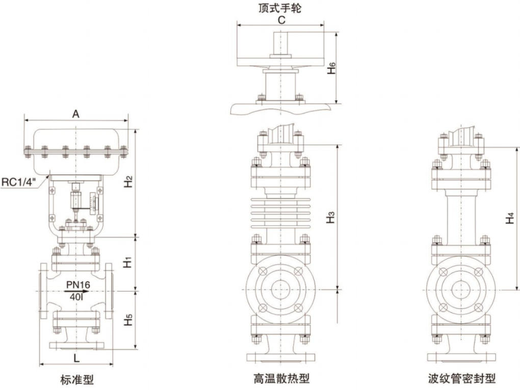
| Dimensions and weight (mm) | ||||||||||||
|---|---|---|---|---|---|---|---|---|---|---|---|---|
| Nominal Diameter | 25 | 32 | 40 | 50 | 65 | 80 | 100 | 125 | 150 | 200 | 250 | 300 |
| L - PN16/40 | 185 | 200 | 220 | 250 | 275 | 300 | 350 | 410 | 450 | 550 | 640 | 720 |
| L - PN64 | 200 | 210 | 235 | 265 | 295 | 320 | 370 | 440 | 475 | 570 | 670 | 750 |
| A | 285 | 285 | 285 | 285 | 360 | 360 | 360 | 470 | 470 | 470 | 580 | 580 |
| H1 - PN16/40 | 155 | 175 | 180 | 200 | 235 | 250 | 260 | 330 | 350 | 420 | ||
| H1 - PN64 | 165 | 175 | 185 | 205 | 245 | 255 | 270 | 335 | 365 | 430 | ||
| H2 | 298 | 298 | 298 | 298 | 380 | 380 | 380 | 510 | 510 | 510 | ||
| H3 - PN16/40 | 235 | 247 | 256 | 268 | 364 | 384 | 394 | 465 | 470 | 540 | ||
| H3 - PN64 | 245 | 265 | 268 | 278 | 381 | 390 | 400 | 470 | 485 | 540 | ||
| H4 - PN16/40 | 364 | 425 | 430 | 445 | 660 | 680 | 690 | 748 | 740 | 780 | ||
| H4 - PN64 | 364 | 425 | 435 | 450 | 665 | 690 | 700 | 750 | 750 | 795 | ||
| H5 - PN16/40 | 140 | 150 | 160 | 180 | 200 | 210 | 220 | 260 | 280 | 320 | 474 | 580 |
| H5 - PN64 | 150 | 170 | 180 | 200 | 220 | 240 | 260 | 300 | 320 | 380 | 474 | 580 |
| C - PN16/40 | - | - | - | - | - | 225 | 245 | 285 | 305 | 350 | 540 | 612 |
| C - PN64 | - | - | - | - | - | 265 | 285 | 325 | 345 | 410 | 540 | 612 |
| H6 | 180 | 180 | 180 | 180 | 236 | 236 | 236 | 310 | 310 | 310 | ||
| Weight (kg) - PN16/40 | 28 | 30 | 39 | 46 | 75 | 81 | 98 | 148 | 188 | 285 | ||
| Weight (kg) - PN64 | 32 | 37 | 49 | 61 | 92 | 98 | 119 | 191 | 222 | 330 | ||
Note:
1. The weights shown in the table are the standard data without attachments. Side-mounted handwheels can also be installed.
2. The flange and the flange end face distance can be manufactured according to the user's specified standards, such as ANSI, JIS, and DIN standards.