
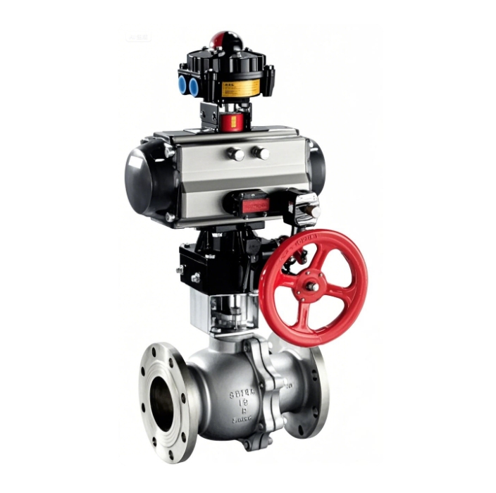
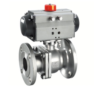
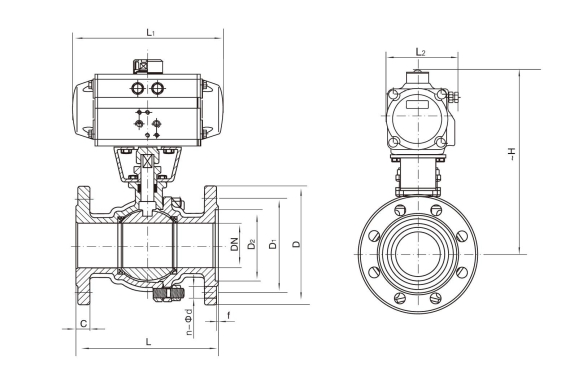
The Pneumatic Actuated Flanged Floating Ball Valve is a versatile and reliable solution for automated flow control in industrial systems. Featuring a full port design and a floating ball, it ensures minimal pressure drop and tight shutoff performance. Constructed with a durable stainless steel body or carbon steel as the body material, this valve is built to withstand harsh conditions and meet fire safe standards. Equipped with a pneumatic actuator, it offers both spring return and double acting operation modes for flexible automation. Integrated limit switches provide precise valve position feedback, making this actuated ball valve ideal for critical applications requiring safety and efficiency.
Model: Q641F (N, P, H, Y)
Size Range: DN15–300mm
Pressure Ratings: 150Lb, 300Lb, 600Lb
Structure: Floating type
Dimensions Standards: GB, ANSI, JIS
Body Materials: Cast steel (WCB), stainless steel (CF8, CF8M, CF3, CF3M)
Sealing Materials: PTFE (F), PPL (P), Nylon (N), Hard alloy (H, Y)
Function Type: Double-acting, single-acting (spring return)
Control Methods: On/off type, regulating type
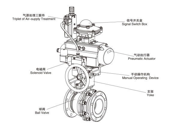
Accessories: Solenoid valve, limit switch, positioner, three-way air treatment unit, manual mechanism or pneumatic actuator ball valve
| Temperature Rating of Seat Sealing Material | ||
|---|---|---|
| Code | Material | Applicable Temperature (℃) |
| F | Reinforced Polytetrafluoroethylene (PTFE) | -40~180 |
| P | Para–position polyphenylene | -40~300 |
| N | Nylon | -20~80 |
| Y | Hard Alloy | -40~425 |
According to the different control and the request can choose the following accessories:
Cut-off Accessories: single electrically-controlled magnetic valve, double electrically-controlled Solenoid valve, signal saver of limit switch.
Adjusting Accessories: electropneumatic positioner pneumatic positioner, electric-pneumatic converter.
Air-supply Treatment Accessories: air-filtering reducing valve, F.R.L. COMBINATION UNIT.
Manual Device: XLHJ Series
| Technique Norm | |
|---|---|
| Design Basis | API, ANSI Standard |
| Design Standard | API 6D, ANSI B16.34 |
| Face to Face Dimension | API 6D, ANSI B16.10 |
| Flange Connecting | API 6D, ANSI B16.10 |
| Connecting Flange Size | ANSI B16.5 |
| Test & Inspection | API 6D, API 598 |
Note:The structural length and connecting flange size of ball valve series can be designed and manufacured as per users'requirements.
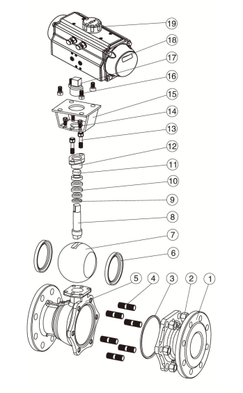
| Form of Main Parts Materials | ||||
|---|---|---|---|---|
| No. | Name of Parts | Material (C) | Material (P) | Material (R) |
| 1 | Right valve | A216-WCB | A351-CF8 | A351-CF8M |
| 2 | Nut | A194-2H | A276-304 | A276-316 |
| 3 | Gasket | PTFE, Graphite metal composite pad | ||
| 4 | Screw | A193-B7 | A276-304 | A276-316 |
| 5 | Body | A216-WCB | A351-CF8 | A351-CF8M |
| 6 | Seat | PTFE, Nylon, PPL, Hard Alloy | ||
| 7 | Ball | A182-F304 | A182-F304 | A182-F316 |
| 8 | Stem | A276-410 | A276-304 | A276-316 |
| 9 | Gasket | A276-304 | A276-304 | A276-316 |
| 10 | Packing | PTFE, Flexible Graphite | ||
| 11 | Bushing | PTFE Composite bearings | ||
| 12 | Gland | A216-WCB | A351-CF8 | A351-CF8M |
| 13 | Screw | A194-2H | A276-304 | A276-304 |
| 14 | Screw | A194-2H | A276-304 | A276-304 |
| 15 | Connecting Yoke | A351-CF8 | A351-CF8 | A351-CF8 |
| 16 | Screw | A194-2H | A276-304 | A276-304 |
| 17 | Connecting Set | A351-CF8 | A351-CF8 | A351-CF8 |
| 18 | Pneumatic Device | AT Series, AW Series | ||
| 19 | Location Indicator | Plastic | ||
Note: The main components and sealing rings of the series ball valves can be designed and selected according to actual working conditions or special user requirements.
| Q641F(N, P, H, Y) - Class 150 Main Outline and Connecting Flange Size | ||||||||||||
|---|---|---|---|---|---|---|---|---|---|---|---|---|
| Nominal diameter | Outline Size | Connecting Flange Size | Actuator Model | |||||||||
| mm | in | L | L1 | L2 | ~H | D | D1 | D2 | C | f | n~Φd | |
| 15 | 1/2 | 102 | 140/159 | 71/83 | 203/240 | 89 | 60.5 | 43 | 10 | 1.6 | 4~Φ15 | AT050D/AT063S |
| 20 | 3/4 | 117 | 141/159 | 71/83 | 209/240 | 98 | 69.9 | 43 | 10.5 | 1.6 | 4~Φ15 | |
| 25 | 1 | 127 | 159/211 | 85/93 | 214/256 | 108 | 79.2 | 51 | 11.5 | 1.6 | 4~Φ15 | AT063D/AT075S |
| 32 | 1 1/4 | 140 | 211/248 | 95/107 | 257/277 | 117 | 88.9 | 64 | 11.5 | 1.6 | 4~Φ15 | AT075D/AT088S |
| 40 | 1 1/2 | 152 | 211/248 | 95/107 | 260/277 | 127 | 98.6 | 73 | 14.5 | 1.6 | 4~Φ15 | AT088D/AT100S |
| 50 | 2 | 178 | 248/269 | 107/123 | 290/300 | 152 | 120.7 | 92 | 14.5 | 1.6 | 4~Φ19 | AT088D/AT100S AT100D/AT125S |
| 65 | 2 1/2 | 190 | 269/345 | 123/152 | 310/335 | 178 | 139.7 | 105 | 17.5 | 1.6 | 4~Φ19 | |
| 80 | 3 | 203 | 269/345 | 123/152 | 346/368 | 191 | 152.47 | 127 | 19 | 1.6 | 4~Φ19 | AT100D/AT125S |
| 100 | 4 | 229 | 345/409 | 152/172 | 410/420 | 229 | 190.5 | 157 | 24 | 1.6 | 8~Φ19 | AT125D/AT145S |
| 125 | 5 | 254 | 409/450 | 178/210 | 457/475 | 254 | 216 | 186 | 24 | 1.6 | 8~Φ22 | AT145D/AT170S |
| 150 | 6 | 305 | 450/500 | 210/252 | 457/511 | 279 | 241.3 | 216 | 25.5 | 1.6 | 8~Φ22 | AT190D/AT210S |
| 200 | 8 | 457 | 533/700 | 330/520 | 583/618 | 343 | 298.5 | 270 | 28.5 | 1.6 | 8~Φ22 | AT240D/AT270S |
Note: The structural length and connecting flange size of ball valve series can be designed and manufactured as per users' requirements. Note: Data XXX/XXX represent respectively the double - acting/single - acting type(spring reposition)of pneumatic actuator Note: The relative sizes are subject to change depending on the differential in valve torque, medium and actuator model Note: the above actuator configuration and data all use soft - seated valves (F, N, P )and hard - seated valves, or consulting us if you have more questions.
| Q641F(N, P, H, Y) - Class 300 Main Outline and Connecting Flange Size | ||||||||||||
|---|---|---|---|---|---|---|---|---|---|---|---|---|
| Nominal diameter | Outline Size | Connecting Flange Size | Actuator Model | |||||||||
| mm | in | L | L1 | L2 | ~H | D | D1 | D2 | C | f | n~Φd | |
| 15 | 1/2 | 140 | 141/159 | 71/83 | 204/235 | 95 | 65.7 | 35 | 14.5 | 1.6 | 4~Φ19 | AT050D/AT063S |
| 20 | 3/4 | 152 | 141/159 | 71/83 | 209/240 | 117 | 82.5 | 43 | 15.8 | 1.6 | 4~Φ19 | AT050D/AT063S |
| 25 | 1 | 165 | 211/248 | 85/93 | 214/256 | 124 | 89 | 51 | 17.5 | 1.6 | 4~Φ19 | AT075D/AT088S |
| 32 | 1 1/4 | 178 | 211/248 | 95/107 | 269/287 | 133 | 98.4 | 64 | 17.5 | 1.6 | 4~Φ19 | AT075D/AT088S |
| 40 | 1 1/2 | 190 | 248/269 | 107/123 | 273/300 | 155 | 114.3 | 73 | 20.6 | 1.6 | 4~Φ19 | AT088D/AT100S |
| 50 | 2 | 216 | 248/269 | 107/123 | 290/300 | 165 | 127 | 92 | 22.3 | 1.6 | 8~Φ19 | AT100D/AT115S |
| 65 | 2 1/2 | 241 | 269/345 | 123/152 | 310/357 | 191 | 149.2 | 105 | 22.3 | 1.6 | 8~Φ22 | AT100D/AT125S |
| 80 | 3 | 283 | 345/409 | 152/172 | 346/368 | 210 | 168.3 | 127 | 23.9 | 1.6 | 8~Φ22 | AT125D/AT145S |
| 100 | 4 | 305 | 409/438 | 172/187 | 418/443 | 254 | 200 | 157 | 30.2 | 1.6 | 8~Φ22 | AT145D/AT160S |
| 125 | 5 | 381 | 438/550 | 178/215 | 470/497 | 279 | 234.9 | 186 | 33.4 | 1.8 | 8~Φ26 | AT160D/AT190S |
| 150 | 6 | 403 | 550/600 | 210/252 | 533/570 | 318 | 266.7 | 216 | 35 | 1.8 | 12~Φ26 | AT216D/AT240S |
| 200 | 8 | 502 | 633/700 | 330/520 | 583/618 | 381 | 320 | 270 | 41.3 | 1.6 | 12~Φ29 | AT240D/AT270S |
Note: The structural length and connecting flange size of ball valve series can be designed and manufactured as per users' requirements. Note: Data XXX/XXX represent respectively the double - acting/single - acting type(spring reposition)of pneumatic actuator Note: The relative sizes are subject to change depending on the differential in valve torque, medium and actuator model Note: the above actuator configuration and data all use soft - seated valves (F, N, P )and hard - seated valves, or consulting us if you have more questions.
| Q641F(N, P, H, Y) - Class 400 Main Outline and Connecting Flange Size | ||||||||||||
|---|---|---|---|---|---|---|---|---|---|---|---|---|
| Nominal diameter | Outline Size | Connecting Flange Size | Actuator Model | |||||||||
| mm | in | L | L1 | L2 | ~H | D | D1 | D2 | C | f | n~Φd | |
| 15 | 1/2 | 165 | 141/211 | 71/95 | 204/235 | 95 | 65.7 | 35 | 14.5 | 6.4 | 4~Φ16 | AT050D/AT075S |
| 20 | 3/4 | 190 | 159/211 | 83/95 | 240/252 | 117 | 82.5 | 43 | 15.8 | 6.4 | 4~Φ19 | AT063D/AT075S |
| 25 | 1 | 216 | 211/248 | 95/107 | 257/265 | 124 | 88.9 | 51 | 17.6 | 6.4 | 4~Φ19 | AT075D/AT088S |
| 32 | 1 1/4 | 229 | 248/269 | 107/123 | 269/287 | 133 | 98.4 | 64 | 20.6 | 6.4 | 4~Φ19 | AT088D/AT100S |
| 40 | 1 1/2 | 241 | 248/315 | 107/141 | 282/292 | 156 | 114.3 | 73 | 22.3 | 6.4 | 4~Φ19 | AT088D/AT115S |
| 50 | 2 | 292 | 269/345 | 123/152 | 300/325 | 165 | 127 | 92 | 25.4 | 6.4 | 8~Φ19 | AT100D/AT125S |
| 65 | 2 1/2 | 330 | 345/438 | 152/187 | 335/357 | 190 | 149.2 | 105 | 28.6 | 6.4 | 8~Φ22 | AT125D/AT160S |
| 80 | 3 | 356 | 409/438 | 172/187 | 368/400 | 210 | 168.3 | 127 | 31.8 | 6.4 | 8~Φ22 | AT145D/AT160S |
| 100 | 4 | 406 | 438/550 | 187/215 | 418/506 | 254 | 200 | 157 | 35 | 6.4 | 8~Φ26 | AT160D/AT190S |
| 125 | 5 | 457 | 550/633 | 215/262 | 445/548 | 279 | 234.9 | 186 | 38.2 | 6.4 | 8~Φ26 | AT190D/AT240S |
| 150 | 6 | 495 | 633/730 | 262/300 | 563/598 | 318 | 269.9 | 216 | 41.3 | 6.4 | 12~Φ26 | AT240D/AT270S |
| 200 | 8 | 597 | 730 | 330 | 636/666 | 381 | 330.2 | 270 | 47.6 | 6.4 | 12~Φ29 | AT270S |
Note: The structural length and connecting flange size of ball valve series can be designed and manufactured as per users' requirements. Note: Data XXX/XXX represent respectively the double - acting/single - acting type(spring reposition)of pneumatic actuator Note: The relative sizes are subject to change depending on the differential in valve torque, medium and actuator model Note: the above actuator configuration and data all use soft - seated valves (F, N, P )and hard - seated valves, or consulting us if you have more questions.